
Piezoelectric vs. piezoresistive accelerometers: working principle
Make the sensing principle, the interfaces and the evidence explicit.
Content reviewed
Three constructions. Two electrical principles.
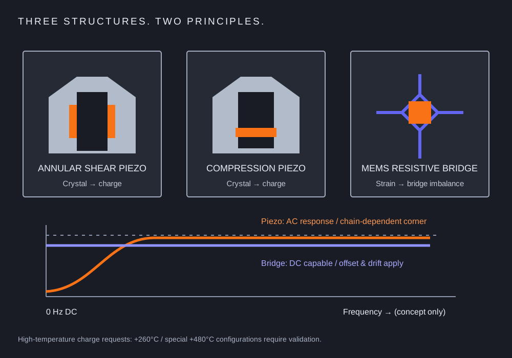
| Decision | Piezoelectric charge | Piezoelectric voltage | Piezoresistive bridge |
|---|---|---|---|
| Transduction | Crystal charge under dynamic load | Crystal charge + integral electronics | Strain changes bridge resistance |
| Signal | pC/g; external charge conditioning | mV/g; matched constant-current input where applicable | Bridge output; calibrated excitation and differential input |
| Static acceleration | Not sustained | Not sustained | DC capable; offset and drift still apply |
| Thermal decision | Sensor, hot-state insulation and cable limits | Integral electronics and complete cable limits | Bridge temperature, excitation and compensation |
Why a piezoelectric accelerometer cannot measure static acceleration
Generated charge leaks through the finite insulation and conditioning network. The low-frequency corner depends on the complete chain and its time constant. A larger time constant supports a longer measurement window, but does not create indefinite DC response.
Sensitivity: pC/g versus mV/g
Calculate sensitivity and independent charge/voltage limits →
For charge sensors, multiply sensor sensitivity in pC/g by converter gain in mV/pC. A hypothetical 10 pC/g sensor with 10 mV/pC conversion gives 100 mV/g. At 14g the predicted peak is 1.4 V and 140 pC; both must fit the conditioner limits. This arithmetic example is not a PZA rating.
Frequency range is an installed-system requirement
Specify the flatness tolerance and mounting condition. Resonance is not the usable bandwidth. Adhesive, fixture stiffness, cable movement, filters and anti-aliasing can change the result. For shock, include rise time and pulse duration as well as peak g.
Choose high temperature by component
Passive charge sensing separates the probe from the electronics. Integral-electronics limits vary by design; a single universal failure temperature is inappropriate. Verify the probe, every cable segment, connector and amplifier at their actual local temperatures.
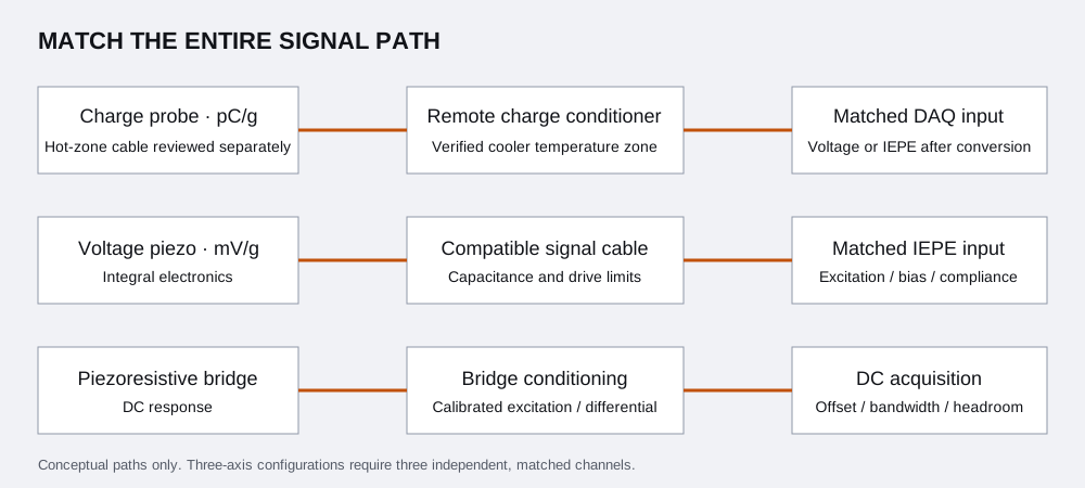
Separate charge decay from shock-induced zero shift.
Finite insulation and the conditioner time constant cause a decaying charge response. Shock-induced offset, clipping and structural resonance are separate possible errors. Review the pulse duration and installed chain rather than assuming all zero changes have the same cause.
For true DC or a long measurement window, review the PZA-PRZ bridge configurations and specify excitation, differential input, damping and zero-offset allowance.
Compare shear and compression under mounting strain.
Construction affects how base bending, thermal gradients and off-axis loads couple into the sensing element. A shear arrangement does not make the installed sensor immune to mounting strain. Compare original base-strain definitions and units, then request the proposed configuration data.
Review low-mass shear mounting or review the hot charge chain with the actual fixture and cable route.
Quote the sensor, channels and calibration scope together.
Quantity, calibrated range, temperature, mounting, connector, cable and conditioning determine the quotation. Request a priced and documented configuration rather than comparing an unqualified sensor-only price.
Temperature. Mass. Pulse. Signal path.
Send the original model and your test conditions. Request a configuration review, CAD and calibration requirements together.
Build your engineering RFQ ↗Compare sensing principles →