High-temperature engine & gas turbine vibration testing.
Keep the charge sensor at the hot test point. Define the cable path, remote conditioning and acquisition together, before committing to a replacement probe.
Owned chain concept. No product dimensions, measured temperatures or released PZA performance implied.
FIRST DECISION / EACH LOCAL LIMIT
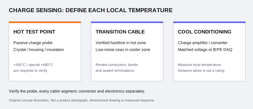
A hot probe does not give the whole chain a temperature rating.
PCB’s high-temperature charge guidance ↗ describes passive charge sensing with external conditioning for engine and turbine tests. The installation decision extends beyond the sensing element: specify continuous exposure, dwell and thermal transients separately for every component.
Location
State in your request
Evidence needed before selection
Probe at test point
Surface/local temperature, dwell, heat-up/cool-down and vibration
Exact sensor configuration; hot sensitivity, insulation and environmental limits
Hot cable run
Temperature along the route, length, bend/strain and exposure
Verified cable construction and termination; review mineral-insulated hardline where required; confirm integral probe exit versus a detachable hot connector
Transition & connectors
Actual joints, if present, local temperature and access
Pinout, sealing, insulation, strain relief and cable-to-cable interface
Remote conditioner
Its own local/enclosure temperature, grounding and power
Input topology, minimum source resistance, charge capacity and output limits
DAQ channel
Input type, coupling, range, sample rate and filter
IEPE excitation/compliance or voltage interface; full-chain usable band
A +260°C or special +480°C probe is a configuration request. It does not release a cable, connector or converter for the same exposure. Cable distance alone does not prove a cooler electronics zone.
Choose the electrical path before choosing an adapter.
A / SINGLE-ENDED CHARGE
Compatible coax → remote conversion
Charge probe + verified low-noise cable
Reviewed charge-to-IEPE converter, or laboratory charge amplifier
Matched IEPE input, or appropriate voltage input
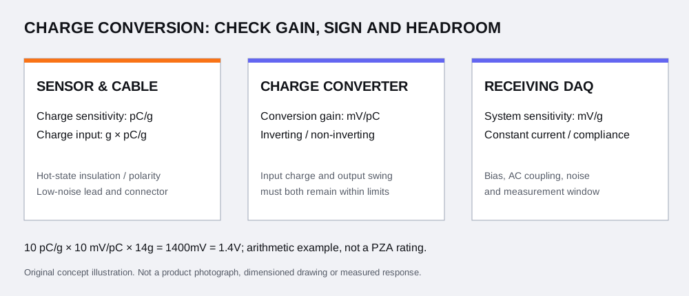
For PZA-422 requests, verify source resistance, input charge, gain, bias, current/compliance and output swing. Review cooler low-noise cable separately from the hot run.
B / BALANCED DIFFERENTIAL
Two signal legs → differential charge input
Verified differential sensor and shielded pair
Compatible differential charge conditioner
Specified conditioner output to the DAQ
Confirm both signal pins, case isolation and shield/ground instructions. A single-ended converter is not automatically a differential solution. The listed PZA-AMP coax configurations do not establish differential-input capability; request that conditioner and its hot-source-resistance compatibility separately.
Review leakage and insulation across the sensor, hot cable and terminations as an assembly. Identify pin-to-pin and pin-to-case values and the test conditions where applicable; do not replace these with a single unexplained resistance number.
The Endevco 6222S datasheet ↗ gives a concrete manufacturer example of a balanced differential charge sensor with its own mating cables and conditioners. It is an original reference, not evidence of PZA interchangeability.
Unknown topology? Keep it unknown in the RFQ and include the connector drawing. Do not assign shield or case as a signal return by appearance.
A sensor that survives the temperature may still be incompatible with the selected conditioner. Endevco TP339, matching and conclusion sections ↗, explains why hot piezoelectric resistance must be checked against the charge amplifier’s input requirements. A room-temperature resistance value alone is insufficient.
Request the sensor/cable assembly’s worst-case hot electrical condition and the conditioner’s specified source-resistance range. Also review thermal-transient response, leakage, connector cleanliness, cable movement and grounding; these are separate from nominal sensitivity arithmetic.
For the dimensional pC/g → mV/g and peak-headroom calculation, use the existing worksheet with your own confirmed values.
Request installed-band evidence, not just a resonance number.
PCB’s charge-mode introduction ↗ separates conditioning-dependent low-frequency response from sensor/mounting high-frequency behavior. Specify the band and amplitude/phase tolerance at the temperatures and mounting conditions that matter to your test.
Review gate
Include in the evidence request
Decision
Mechanical installation
Controlled mounting drawing, surface, fasteners/torque, base strain, orientation and cable restraint
Resolve access and mounted-response constraints before ordering interfaces
Electrical & thermal
Probe and cable hot insulation, connector pinout, case isolation, conditioner source resistance and local temperatures
Resolve topology and hot compatibility before committing to a converter
Dynamic acquisition
Frequency band/tolerance, peak/transients, charge and voltage limits, sample rate, anti-alias filtering and channels
Confirm the usable complete-chain measurement window
Documentation & supply
Exact model/revision, ambient vs elevated-temperature calibration scope, uncertainty/traceability, CAD and quotation
Agree the supplied evidence and acceptance conditions in the order
For speed-referenced order tracking during a run-up or coast-down, include the available speed/phase reference and channel synchronization requirements. NI’s order-analysis explanation ↗ shows why speed context belongs with the vibration data; this page does not assume a tachometer or analysis method is supplied.
01
Map the run
Point, axes, temperature/time, frequency and amplitude.
02
Match the chain
Mount, local cable route, hot insulation, conditioner and DAQ.
03
Agree the evidence
Controlled documents, calibration conditions and supply confirmation.
Permanent monitoring or protection is a separate system task. Kistler’s 8209A monitoring page ↗ illustrates how such equipment has its own installation and approval scope. This PZA page offers a test-instrumentation review, not a monitoring-system approval.
ENGINE TEST SELECTION QUESTIONS
Resolve the hot-chain questions before requesting CAD.
Can I keep an existing IEPE acquisition card?
Possibly. A compatible single-ended charge sensor can feed a reviewed charge-to-IEPE converter in a verified cooler zone. Check hot sensor insulation, input charge, gain, current, compliance voltage, bias and bandwidth. A matching connector alone does not establish compatibility.
Does moving the converter two metres away make it cool enough?
No fixed distance guarantees local temperature. Provide the actual cable route, heat exposure, enclosure conditions and conditioner temperature during the intended run. Every segment and termination needs its own review.
Can a two-pin differential charge sensor use a coax adapter?
Do not assume that it can. A balanced differential output needs a compatible differential input and a verified shield/ground and pinout scheme. Do not ground one signal leg or treat the shield as a signal return without the selected equipment instructions.
Why request insulation resistance at the hot operating point?
The resistance seen by a charge amplifier can fall as the sensing element gets hotter. Match the worst-case hot source resistance to the conditioner’s specified input requirements; a room-temperature insulation check alone does not establish hot compatibility.
Is a 480°C sensor request also a 480°C cable rating?
No. Probe, hot cable, transition, connector and electronics have separate limits. A +480°C PZA request requires controlled configuration and calibration confirmation. No PTFE extension or converter inherits the probe temperature request.
Can the highest resonance frequency be used as test bandwidth?
No. Specify a usable installed band with an amplitude/phase tolerance. Mounting, cable restraint, filtering and the full signal chain affect the measured response; a resonance value is not a flat-band limit.
What should I provide for run-up or coast-down order tracking?
State the speed range, required orders, available speed or phase reference and synchronization with vibration channels. Speed-referenced analysis is an acquisition and processing requirement; ordering an accelerometer alone does not supply or qualify that complete system.
Does this page qualify permanent monitoring or a turbine protection system?
This page covers a test-instrumentation request. Permanent monitoring, alarms, hazardous-area use and protection duties have additional equipment and system requirements that must be reviewed separately. No such system approval is offered here.
Which calibration and installation documents should I request?
Ask for the exact part and revision, connector/pinout, installation instructions, charge sensitivity and frequency response, hot electrical/thermal evidence, conditioner limits, and calibration conditions/uncertainty/traceability. State whether you need ambient or elevated-temperature characterization.
Can you quote a direct replacement and a delivery date from this page?
Send the full original suffix, drawing and operating conditions. PZA identifiers are request configurations pending technical and supply review. Compatibility, price, delivery and available CAD/calibration documents are confirmed in the quotation.
APPLICATION RFQ / PZA-CHG + PZA-AMP
Send the run conditions with the measurement chain.
The editable test brief begins with unknowns. Replace them with your actual conditions, including a local temperature for each segment, and select only the accessories you want reviewed.
No hardware profile, connector topology or conditioner is pre-approved. Request controlled drawings and calibration scope together with the quotation. Elevated-temperature dynamic calibration is a separate feasibility and quotation request, not a default deliverable.
Use the product-family pages for a specific catalog configuration. PZA-422 requests apply to a compatible single-ended charge path; keep conditioning under review while the input topology is unknown.
Technical content reviewed 9 November 2026. Manufacturer sources explain principles and original equipment; they do not validate PZA supply specifications.