Specified excitation
Calibration voltage, current/power budget, warm-up and bridge resistance.
 PZAQUARTZ & CERAMIC DYNAMICS
Specify more than peak g. Match pulse duration, rise time, damping and a calibrated bridge channel before requesting a piezoresistive accelerometer replacement.
PZA-PRZ requests up to ±50,000g are planning targets. Pulse, mounting, calibration and separate survival conditions require confirmation.
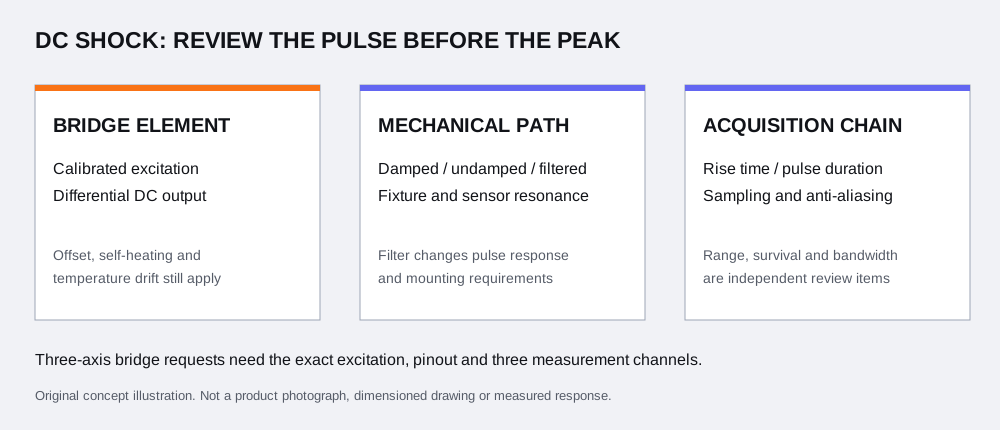
Use the expected waveform and required measurement result to define the channel. A requested range, a shock-survival limit and a natural frequency describe different properties; none replaces a usable response with stated tolerances.
| Requirement | Include in your brief | Selection consequence |
|---|---|---|
| Peak and direction | Positive/negative peak, off-axis loading, repeated events | Linear range and complete input headroom; separate overload/survival review |
| Duration and rise time | Pulse shape, width in ms/µs, rise time or an existing waveform | Required dynamic response, possible resonance excitation and damping review |
| Frequency and result | DC/lowest frequency, upper band/tolerance; waveform, SRS or integrated result | Installed sensor, conditioning, acquisition and processing considered together |
| Mount and environment | Seismic-mass location, fixture, restraint, temperature/time and cable path | Mechanical interface, base strain and thermal/zero behavior for the exact installation |
The Endevco 7270A datasheet ↗ lists measurement range, resonance, shock limit and zero-related characteristics separately. These original specifications are not PZA ratings or a substitute for the full model suffix.
Review PZA-PRZ request configurations →Calibration voltage, current/power budget, warm-up and bridge resistance.
Excitation/signal pairs, polarity, case/shield and restrained lead.
DC coupling, gain, initial offset, common-mode and differential input limits.
Analog anti-alias response, per-channel sampling, trigger and data window.
PCB’s MEMS/PR guidance ↗ explains the bridge readout and calibrated-excitation requirement. A charge amplifier or charge-to-IEPE converter serves a different sensor output; it does not replace the bridge channel.
Endevco’s excitation discussion ↗ describes why self-heating and zero output must be considered when excitation changes. Identify whether sensitivity is mV/V/g, or mV/g at a stated voltage. A dimensional rescale alone does not confirm calibration.
Keep unknown excitation, pinout and DAQ limits under review. Do not infer an excitation voltage, wire color assignment or amplifier capability from another model.
| Mechanism | What to review | What it does not establish |
|---|---|---|
| Internal sensor damping | Resonant amplification, usable response and specified damping | Universal pulse fidelity or interchangeability with an undamped model |
| External mechanical isolator/filter | Installed transfer, mounting coordinates, added mass and environment | The same mechanical input or response as the bare sensor |
| Analog filtering | Location in the chain, passband/phase, input limits and anti-alias response | Protection for a sensing element or earlier stage already overloaded |
| Digital processing | Saved raw data, filter settings, baseline and reporting method | Recovery of clipped, aliased or mechanically corrupted information |
The PCB damped-PR development paper, abstract and introduction ↗ describes resonance amplification as an engineering problem and damping as a tradeoff. It does not supply a universal filter recommendation for your event.
The Endevco 7264H datasheet ↗ is a specific damped crash-channel example. Keep H, C, undamped and mechanically isolated variants distinct; model-family resemblance does not release a PZA replacement.
Warm-up, excitation, offset, temperature and a defined pre-trigger window.
Verify complete channel limits, synchronization, trigger and analog acquisition.
Post-event offset, electrical health and any required recalibration under agreed conditions.
TE’s MEMS DC overview ↗ distinguishes DC sensing and damping considerations. For this request, record initial and post-event zero separately. DC capability does not guarantee zero drift or error-free velocity/displacement integration.
For SRS or integrated results, supply the required processing definition and observation window. Peak and duration alone cannot uniquely describe the waveform or its result. Digital baseline correction must be documented with the raw record; it is not proof that the sensor channel remained linear.
Compare piezoelectric and piezoresistive response →| Request example | Review next | Still unknown |
|---|---|---|
| Crash channel: ±200g, 15ms event | Required DC/low-frequency content, damped response, mounting and bridge/DAQ conditions | Actual rise time, usable band/tolerance, offset and program acceptance |
| Impact channel: 2,000g, 0.5ms event | Linear range versus overshoot/survival, damping, signal headroom and acquisition | Full waveform/spectrum, rise time, mount and calibrated excitation |
| High-G event: 20,000g peak, duration unknown | Obtain pulse/time-history requirements before selecting a channel | No bandwidth, damping, range reserve or survival condition is assigned from peak alone |
All three are illustrative customer requirements. No PZA measurement, supplied range, customer case or test qualification is demonstrated.
Send your actual pulse and channel requirements →The 7270A original datasheet identifies a fixed-resistor option. PZA-7270-Z and shunt requests need their own electrical definitions; neither substitutes for a moving sensing element or a mechanical calibration. Confirm bridge resistance, excitation, resistor arrangement and the purpose of the electrical check.
| Document or check | State the required conditions |
|---|---|
| Controlled mechanical drawing | Exact suffix/revision, mounting footprint, seismic-mass location, fasteners, cable restraint and any isolator |
| Electrical and calibration record | Sensitivity with units/excitation, input/output resistance, offset, polarity, temperature conditions and traceability/uncertainty scope |
| Dynamic and overload evidence | Usable band/tolerance, damping/installed response, linear range, separate survival pulse conditions and post-event checks |
| Acquisition and processing | DAQ/differential/common-mode limits, analog filter, sampling/trigger, saved raw record and declared processing |
No. Include pulse duration, rise time, shape/spectrum, required band and tolerances, mounting, off-axis loading and acquisition conditions. Linear range and survival must be reviewed separately for the proposed configuration.
No. DC response does not remove initial offset, thermal effects, self-heating or post-event zero changes. Specify pre-event and post-event observation windows and the allowed baseline change.
A raw piezoresistive bridge needs its specified excitation and compatible differential conditioning. A charge-to-IEPE converter does not perform bridge excitation/readout. Check the selected conditioner output before connecting the DAQ.
Use the excitation documented for the calibration. Output sensitivity may be expressed per volt of excitation, but self-heating and zero changes can make a simple voltage rescale insufficient. A different excitation is a calibration/configuration review.
Its mechanical transfer changes the signal reaching the sensing element. Internal damping, an external isolator and electrical filtering are different mechanisms. Review their complete response against the required pulse band; no universal filter is selected here.
It cannot undo mechanical damage or recover information already lost to sensor, conditioner or ADC saturation. Record the analog anti-alias path and input limits separately from later digital processing.
No. Surviving an overload does not establish a linear or calibrated reading during that overload. Request the stated pulse conditions, range and post-event checks for the exact sensor and mounting.
These are electrical-path review requests. A shunt needs its circuit and resistor conditions; a fixed-resistor dummy does not reproduce the moving sensing element. Neither supplies a mechanical acceleration calibration or proves the fixture response.
They do not uniquely define the waveform. State the time history or spectral requirements, processing settings, baseline method and integration window. DC capability alone does not remove offset or integration error.
Request the exact suffix/revision, mounting and seismic-mass coordinates, lead/pinout/polarity, excitation-specific sensitivity/offset and resistance data, usable response, separate survival conditions and calibration scope. Any program-specific acceptance requirements must be agreed in the quotation.
Replace the unknown entries with your actual pulse, bridge and acquisition requirements. Specify what must remain unknown for review. No profile, excitation voltage or accessory is preselected.
Use the product-family page for a specific catalog request. Calibration capability, controlled drawings, price, delivery and any program-specific acceptance must be agreed in the quotation.
Technical content reviewed 9 November 2026. Original manufacturer examples explain decisions; they do not validate PZA ratings or supply evidence.